Motivation: Develop a numerical simulation using Onsager's Pancake Approximation for fluid flow in gas centrifuges for comparison with a full 3D simulation resolving all the complicated physics.
In the summer before I came to UCSD I interned at Lawrence Livermore National Laboratory where I implemented a numerical model of Onsager's pancake
approximation for fluid flow in gas centrifuges.
Gas centrifuges are extremely complex physical systems containing hypersonic flow, shock waves, extreme centrifugal forces and density gradients,
and complex geometry. A full 3-D numerical simulation resolving all the complicated physics is challenging to develop and computationally
expensive to run. Validation is challenging due to the lack of experimental data available for comparison due to extreme
difficulty in making experimental measurements.
Onsager's pancake approximation simplifies the flow physics significantly by considering the flow to be a perturbation to solid-body rotation.
In the axisymmetric plane, the fluid is treated as subsonic and incompressible. Assuming the centrifuge is long, end effects can be simplified by
using slip boundary conditions at the top and bottom instead of having to resolve or model the effect of boundary layers.
Beginning with linearized equations for mass, momentum, and energy conservation together
with the equation of state for an ideal gas, after manipulation one governing sixth order partial differential equation for the master
potential function is obtained.
The governing sixth-order partial differential equation was broken into three coupled second-order
partial differential equations and then solved numerically.
For further details on this work, see the technical report of de Stadler and Chand (details on publications page).
 |
|
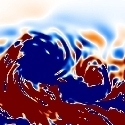
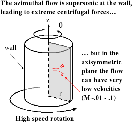
| Simplified gas centrifuge setup. Simulations were performed in the axisymmetric plane shown in gray. | Streamlines for a case with a wall speed of 500 m/s. Note that the wall is on the left and the flow is moving counter-clockwise. The horizontal scale is given in scale units (see technical report for details) which gives the illusion that flow occurs over a fairly large region of the radial domain. In actuality, the flow is highly concentrated in the near wall region due to centrifugal effects. |
 |
|
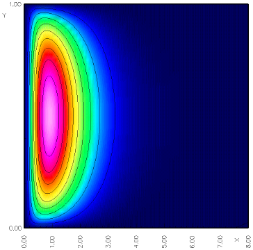
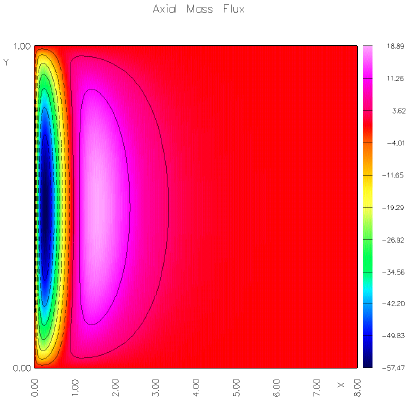
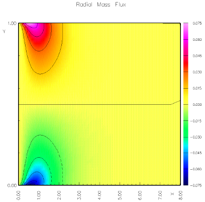
| Axial mass flux. | Radial mass flux. Note that positive r is to the left. |