Motivation: Recent advances in cellular materials allow for the construction of increasingly complex structures down to a very small scale.
Given these recent advances, how does one design an optimal heat sink based on geometrical considerations independent of working
fluid and heat sink material?
A heat sink is a device which transfers heat from a hot area to another area, often using a working fluid to transport excess heat away from the hot area.
Heat sinks are found in a wide variety of applications ranging from nuclear power plants to personal electronics.
One particularly interesting application is using heat sinks to manage the extreme heat generated on the airframe by hypersonic vehicles.
The need to provide cooling for hypersonic vehicles combined with recent advances in cellular materials which allow for the consideration of
increasingly complex designs provided motivation for this work.
To analyze this problem, the principle of superposition was used to reduce the geometry of a heat sink to a repeating cell. Assuming a certain
percentage of the volume is available for channels for fluid to pass through, where should one place the channels? What shape should they be?
How many channels should be used? To answer these questions, an analytic approach was taken with testing being performed using computational
fluid dynamics software. Models were built using SolidWorks and then simulations were performed using CFDesign, a commercially available
computational fluid dynamics software package.
Initial testing was performed on a 2D block without a working fluid to analyze the effect of conduction within the solid material for different
channel geometries and placements.
Next three-dimensional effects were included by considering a 3D block with a working fluid. Simulations were performed to develop a better
understanding of the relationship between input parameters such as the mass flow rate and output parameters such as the temperature at critical
locations. After general performance trends were observed, work began on developing an optimization framework.
To develop an optimal design, it is necessary to develop a performance metric to rank different heat sink designs. An optimal heat sink should
Using this criteria, a performance metric was developed and used to rank different designs. Unfortunately, results were inconclusive and it was
determined that a different approach was needed.
Next, the focus shifted from general heat sink optimization to optimization in the case of a thin walled square channel.
For this work, the square channel was discretized and represented as a thermal network. The thermal network uses an analogy with electric resistance
networks which have proven useful as a way to solve heat transfer problems. Another advantage of thermal networks is that they are well suited to
numerical computation. Due to time constraints, the work using the thermal network did not advance past the set up phase.
While results were inconclusive, this experience was a good introduction to performing independent research.
For further details on this work, see my senior thesis. pdf
 |
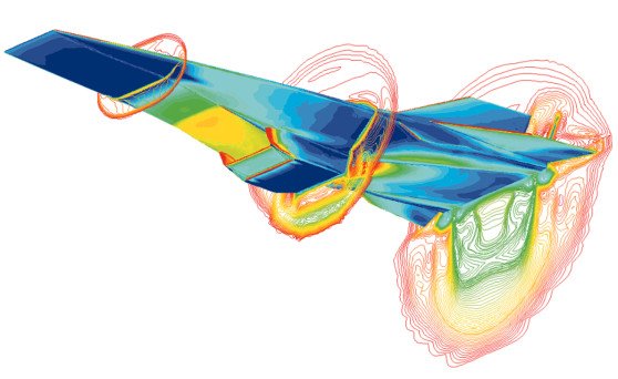 |
| Cellular materials. (a) aluminum honeycomb. (b) paper-phenolic resin honeycomb, (c) ceramic honeycomb with square cells, (d) ceramic honeycomb with triangular cells. Image from Gibson and Ashby, "Cellular Solids: Structure and properties" 2nd edition. | Results from a Computational Fluid Dynamics (CFD) simulation showing the heat flux over the Hyper-X airframe while moving at Mach 7 with the engine operating. Red shows highest heating, blue shows lowest heating. Image from NASA Dryden Flight Research Center. NASA image source page |
 |
 |
| Repeating cell concept. | Boundary conditions. |
 |
 |
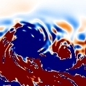
| Temperature profile in the axial direction for flow in a square duct. Red is hot and blue is cold. The top image shows a case where the mass flow rate is too high, the middle shows a case where the exiting fluid becomes fully hot at the exit, and the bottom shows a case where the mass flow rate is too low and the fluid and solid become too hot. | Images showing a sample thermal network. The red dots are computational nodes. |